Outdoor Calibration 2022
5G-LENA simulator has been calibrated under 3GPP reference results for NR-based outdoor deployments as defined by ITU in the Report ITU-R IMT-2020 [ITUR2020]. The results obtained by companies in 3GPP for the scenarios are defined in [M2412] and [Huawei].
The scenarios considered for calibration are the Rural-eMBB, configuration A and B, and the Dense Urban-eMBB configuration A. All the details related to the configuration parameters can be found in [SimpatKoutlia], while the 5G-LENA release that includes the code to reproduce the calibration results is the v2.3.
Network Topology and KPIs
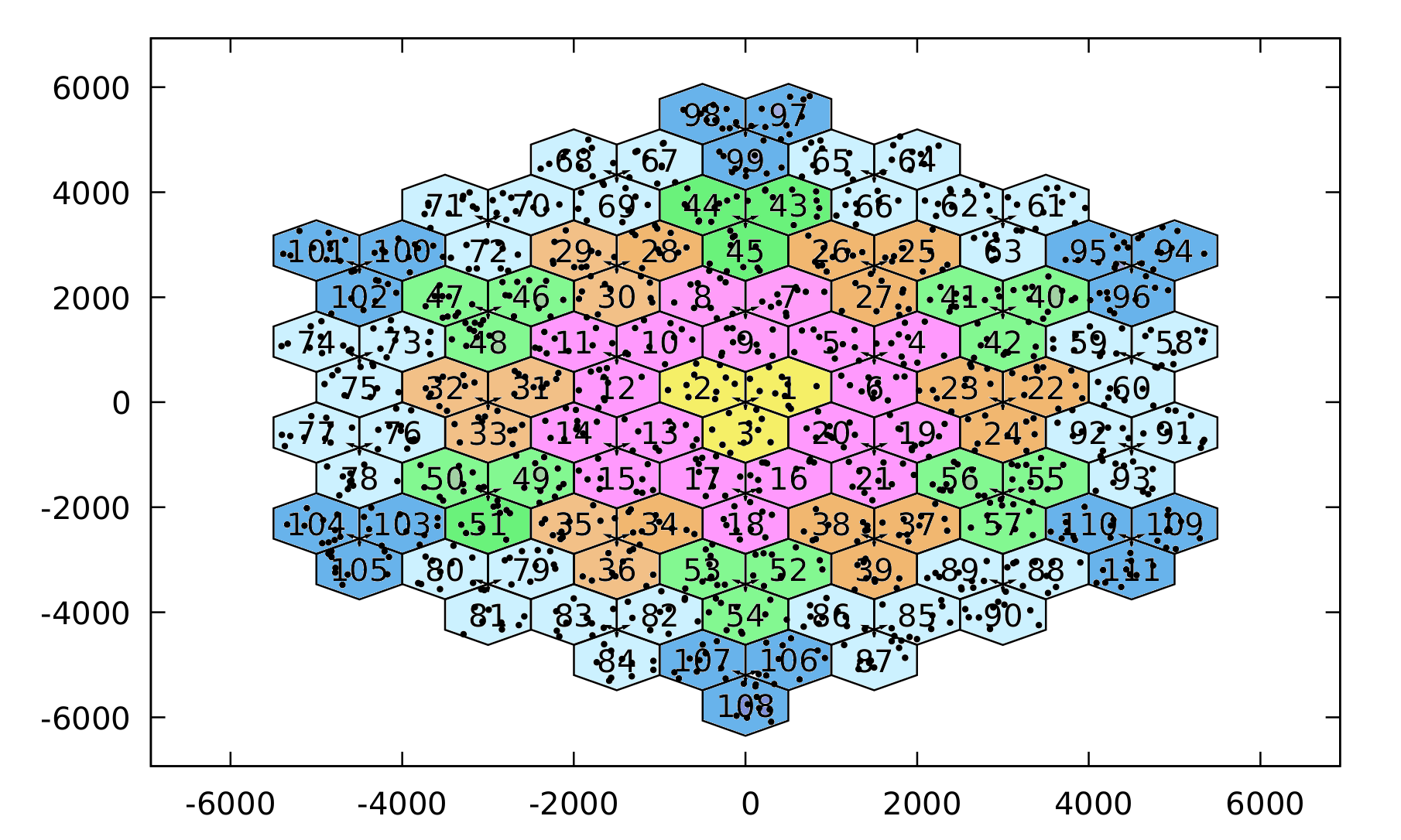
The network layout consists in a hexagonal topology with 37 sites of 3 sectors each, thus leading to 111 Base Stations (BS). However, in the measurements we consider only the 21 inner BSs, while the 111 BSs are simulated to account for the wrap-around effect. The Key Performance Indicators (KPIs) used for the evaluation of the candidate radio interface technologies are the Coupling Gain and the Downlink Geometry. According to [Nomor] the Coupling Gain includes the pathloss, the antenna gains and the average fast fading, while it excludes processing gains such as the ones obtained by beamforming techniques, except for analog beamforming gains of the transmission/reception units (TXRUs) where applicable. The Downlink Geometry is also described in [Nomor] as the ratio of received signal power to the sum of interference and noise power where all signals are averaged individually over the used bandwidth. Similarly to the Coupling Gain, the Downlink Geometry does not include any processing gain at transmitter or receiver except with analog beamforming where applicable.
Let us notice that for the calibration of the simulator, the following features have been implemented, included in 5G-LENA release v2.3:
- Extension of the 3GPP SCM to include O2I Losses
- Support of wrap-around technique
- Support of 3D user deployment
- Dual-polarized antennas and beam sets
Outdoor Simulation results
System-level E2E simulation results based on the Downlink Geometry and Coupling Gain are presented in the next figures. Notice that we focus on the Rural-eMBB configuration A and B, however all the simulation results can be found in [SimpatKoutlia].
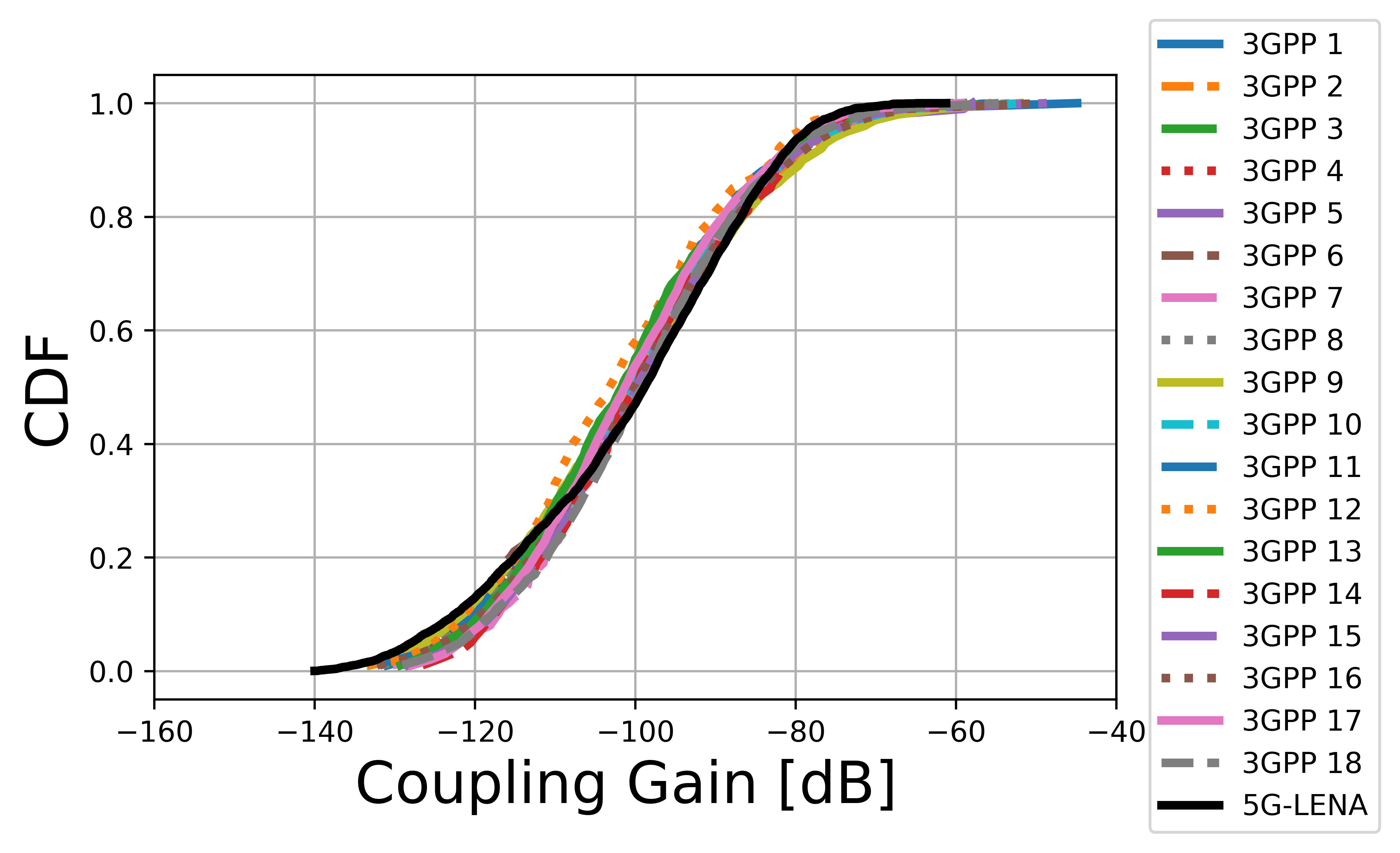
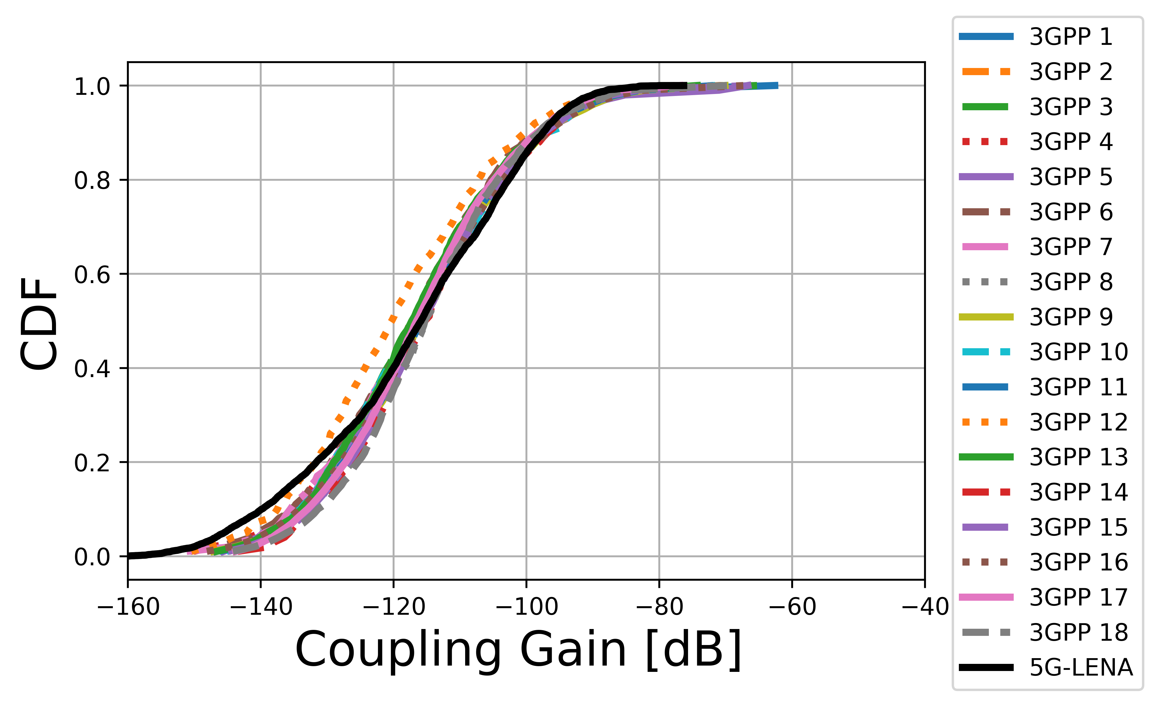
From the figures it can be clearly seen that the 5G-LENA simulator achieves very similar performance as the benchmark simulators with respect to both KPIs and that it meets the key technical performance requirements. The resemblance of the results with that provided by 3GPP proves that the simulator is analogous to industrial or private ones and can be used by the research community for the development, study and evaluation of existing and/or new features.
Indoor Calibration 2018
5G-LENA simulator is calibrated according to Phase 1 indoor hotspot system-level calibration for multi-antenna systems, as per Annex A.2 in [TS38802]. Details of the evaluation assumptions for Phase 1 NR MIMO system level calibration are provided in [R11703534], with further clarifications in [R11700144], and are summarized in what follows.
Simulation parameters and deployment
The deployment scenario is composed of 12 sites at 20 m distance, and 120 UEs (100% indoor) randomly dropped in a 50 m x 120 m area. Simulation parameters are:
- Carrier frequency: 30 GHz
- Mode: downlink only
- Bandwidth: 40 MHz
- Sub-carrier spacing: 60 kHz
- Channel model: Indoor TR 38.900
- gNB transmit Power: 23 dBm
- gNB antenna configuration: M=4, N=8 (32 antenna elements), 1 sector, vertical polarization
- UE antenna configuration: M=2, N=4 (8 antenna elements), 1 panel, vertical polarization
- gNB antenna height: 3 m
- UE antenna height: 1,5 m
- gNB noise figure: 7 dB
- UE noise figure: 10 dB
- UE speed: 3 km/h
- Scheduler: TDMA PF
- Traffic model: full buffer
Indoor Simulation results
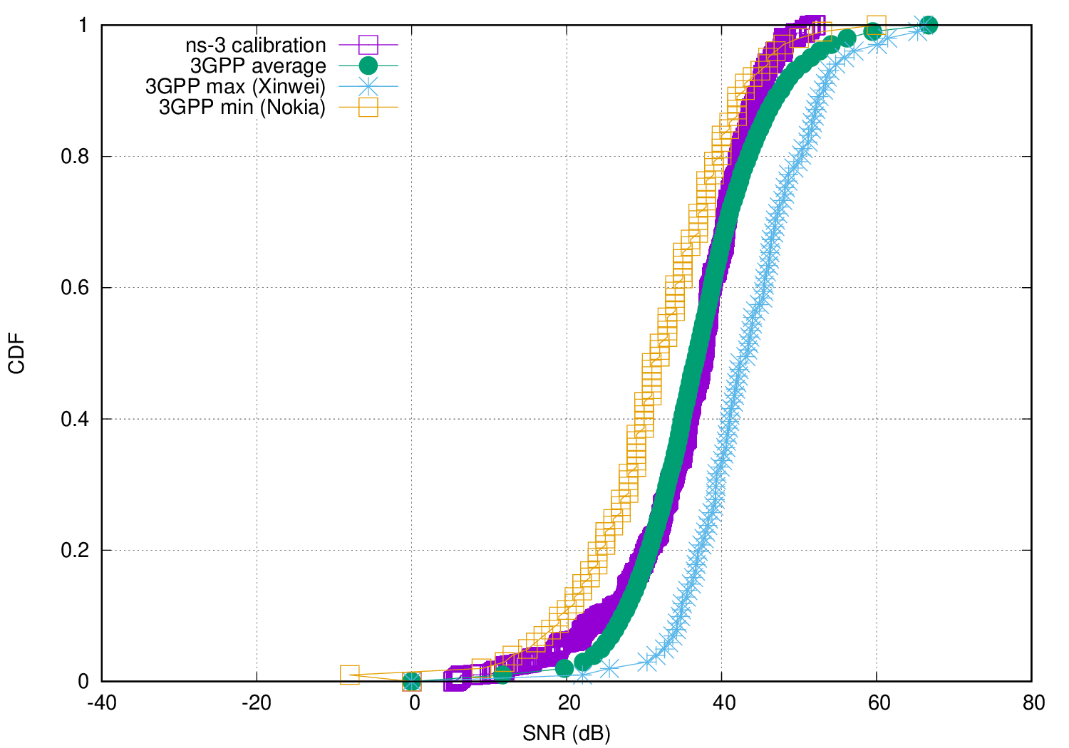
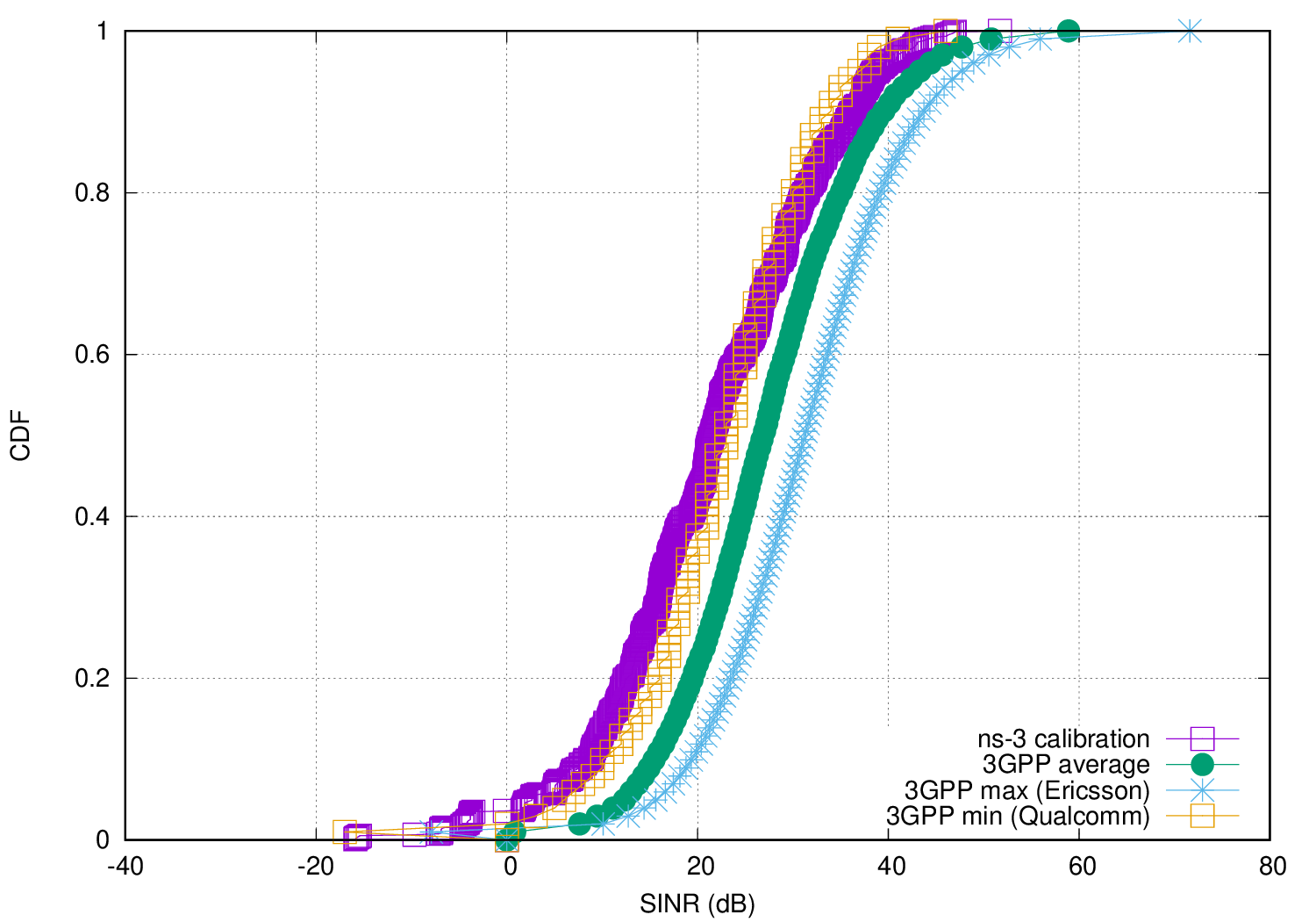
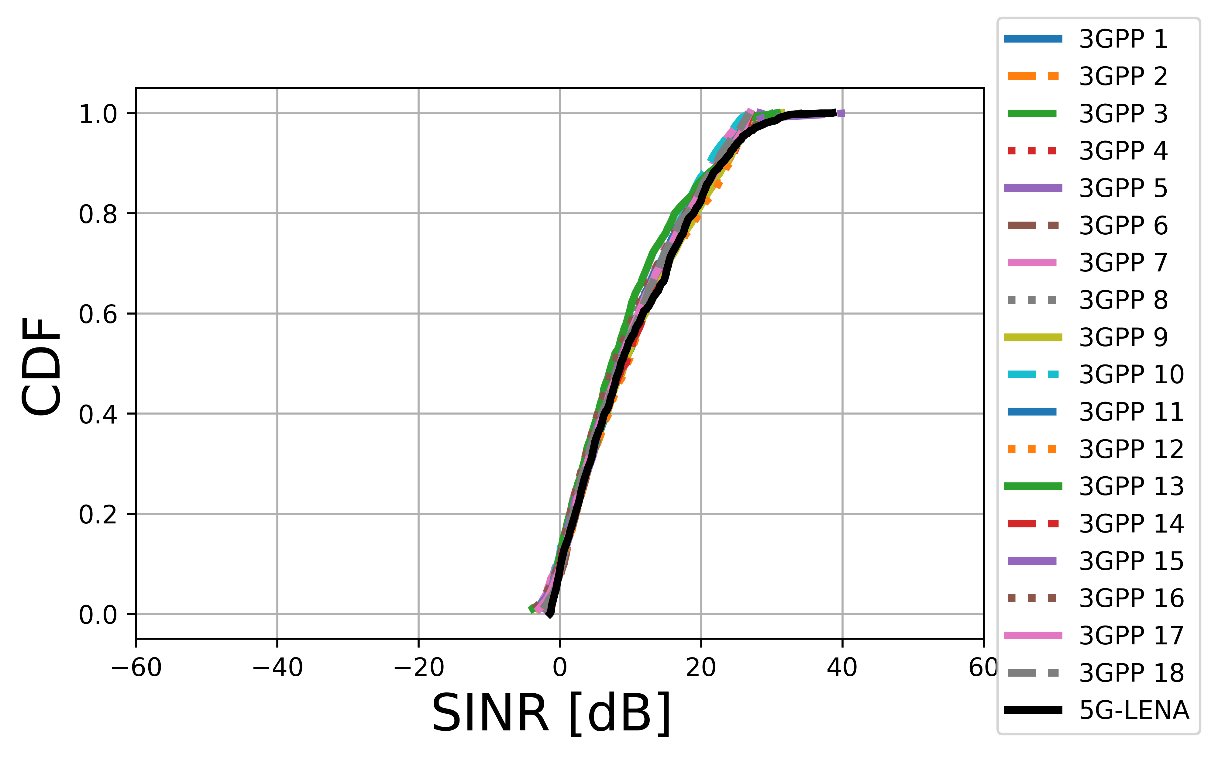
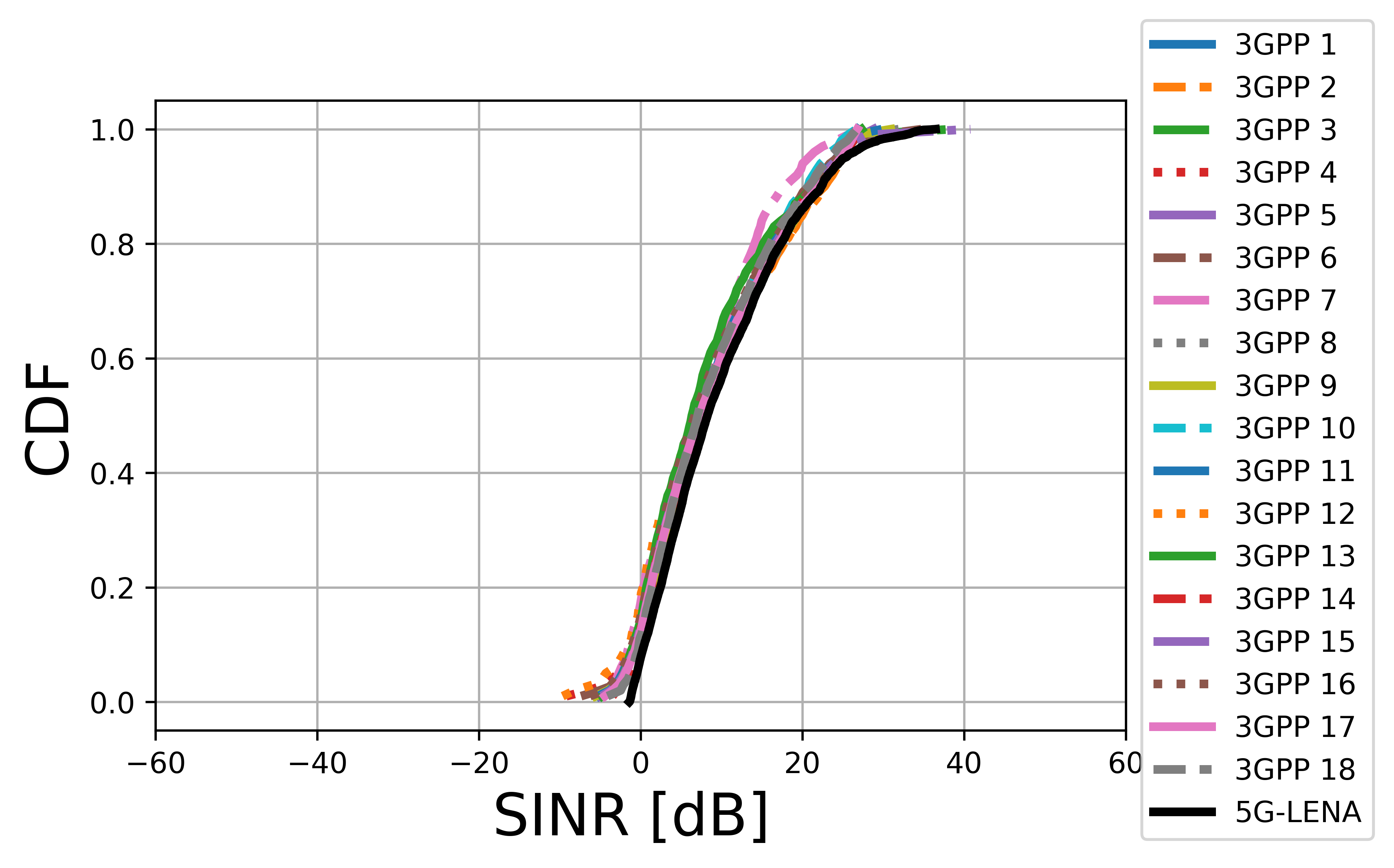
As reference curves, we use the results provided by the companies in [R11709828]. We consider the CDF of the wideband SINR with beamforming, and the CDF of the wideband SNR with step b (i.e., with analog TX/RX beamforming, using a single digital TX/RX port). For each case, we depict as reference the average of the companies contributing to 3GPP as well as the company that gets the minimum and the maximum of the average wideband SNR/SINR, so that a region for calibration is defined.
We have tested different configurations, varying the InH path loss model {InH office-mixed, InH office-open, InH shopping-mall}, shadowing {enabled, disabled}, gNB antenna orientation {Z0-plane, X0-plane}, beamforming method {optimal, beam search}, gNB element antenna model {3GPP single-sector, 3GPP wall-mount, ISO}, and UE element antenna model {3GPP, ISO}. In the following figures, we depict the CDF of wideband SNR and SINR, for a configuration that matches the 3GPP calibration region. We can see that the SINR is close to the lowest 3GPP reference curve. Regarding SNR, it lies entirely within the 3GPP calibration region, with a perfect match with the average 3GPP SNR.