NR frame structure and numerologies
Our implementation currently supports the 5G NR numerologies shown in the following [TS38300]:
| Numerology | Slots per subframe | Symbol length (μs) | Slot length (ms) | Subcarrier spacing (kHz) | Symbols per slot |
|---|---|---|---|---|---|
| 0 (LTE) | 1 | 71.42 | 1 | 15 | 14 |
| 1 | 2 | 35.71 | 0.5 | 30 | 14 |
| 2 | 4 | 17.85 | 0.25 | 60 | 14 |
| 3 | 8 | 8.92 | 0.125 | 120 | 14 |
| 4 | 16 | 4.46 | 0.0625 | 240 | 14 |
In order to simplify the modeling, the cyclic prefix is included in the OFDM symbol length. For example, for numerology 0, the OFDM symbol length is 1ms/14=71.42μs, while the real symbol length is 1/SCS=66.67μs and the cyclic prefix is 4.76μs. A slot can contain all downlink, all uplink, or at least one downlink part and uplink part. Data transmission can span multiple slots.
FDM of numerologies
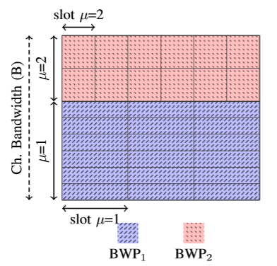
When numerologies are multiplexed in a frequency domain, a.k.a., frequency division multiplexing (FDM) of numerologies, each numerology occupies a part of the whole channel bandwidth, which is referred to in NR as a bandwidth part (BWP) [TS38300]. This is useful to achieve energy saving purposes, as well as for a gNB to accommodate different services with different latency/throughput requirements, as eMBB and URLLC, within the same channel bandwidth.
The ‘NR’ module supports orthogonal and static FDM of multiple numerologies. An example is shown below for two numerologies.
Mini-slot and mixed UL-DL slot format support
According to the NR definition of TTI, one TTI duration corresponds to a number of consecutive OFDM symbols in the time domain in one transmission direction, and different TTI durations can be defined when using different number of OFDM symbols (e.g., corresponding to a mini-slot, one slot or several slots in one transmission direction) [TS38300]. We define a slot as a period of time containing 14 OFDM symbols (which time length depends on the selected numerology). Each OFDM symbol can contain UL/DL control/data. By default, the first OFDM symbol in a slot is devoted for DL control, the last OFDM symbol to UL control, and the OFDM symbols in between can be dynamically allocated to DL and/or UL data.
The ‘NR’ module supports a dynamic UL-DL slot format [TS38213].
Propagation models
Our implementation currently supports the following path loss models: Indoor-Hotspot (InH) Office-Open, InH Shopping-Mall, InH Office-Mixed, Rural Macro, Urban Macro, Urban Micro Street-Canyon. Line-of-Sight (LOS) and non-LOS (NLOS) conditions can also be enforced.
Outdoor-to-indoor propagation losses and autocorrelation of shadow fading are also included. As additional modelling components there is spatial consistency and blockage, but not oxygen absorption.
Channel models
Fast fading follows step-by-step the 3GPP channel model as per [TR38900].
Antenna element radiation pattern
Isotropical radiation pattern of the antenna elements, as well as 3GPP models are supported. For the 3GPP element radiation pattern, the vertical and horizontal radiation patterns are obtained as in [TR38802] (table A.2.1-8 for UE, and table A.2.1-7 for gNB).
Antenna array
A planar antenna array is used both at gNBs and UEs. Uniform planar (rectangular) arrays are supported. Dual-polarization is supported. Multiple panels for the UE are also supported.
Beamforming methods (array radiation pattern)
The ‘NR’ beamforming model supports two types of analog beamforming algorithms: ideal and realistic. Ideal analog BF methods determine the BF vectors based on either the assumption of the perfect knowledge of the channel (e.g., cellScan or Kronecker methods, which do test a set of predefined beams and select the beam-pair providing a highest average SNR), or the exact positions of the devices (e.g., directPath method, which uses the angle of arrival/departure to generate the beam-pair), and they do not consume any time/frequency overhead to design the BF vectors. On the other hand, realistic analog BF methods, select the best BF based on a channel estimate that is obtained from actual Sounding Reference Signals (SRSs) reception. So, SRS resources are spent to get the channel estimate and then do beamforming.
Our simulator supports abstraction of the analog beam ID through two angles (e.g., azimuth and elevation in cellScan method). A new interface allows you to have the beam ID available at MAC layer for scheduling purposes.
For what regards to the digital beamforming, we follow the Precoding Type I, defined for Single User MIMO systems in 3GPP NR.
NR PHY abstraction
The ‘NR’ module includes a new PHY abstraction model for data that accounts for LDPC coding and extends the modulations up to 256-QAM, as compared to the one in ns-3 LENA that used Turbo Codes (TC) and up to 64-QAM. The developed model capitalizes on the exponential effective signal-to-interference-plus-noise ratio (SINR) mapping (EESM), for which the optimal effective SINR mapping parameters are derived with a calibration procedure using an NR-compliant link-level simulator. The NR-compliant link-level simulator has also been used to obtain lookup tables of block error rate (BLER) vs SINR for various NR configurations (e.g., different MCSs, MCS tables, and resource allocations). The developed PHY abstraction model supports HARQ based on Incremental Redundancy and on Chase Combining. Both MCS Table1 (up to 64-QAM) and MCS Table2 (up to 256-QAM) in NR are supported [TS38214] and the transport block segmentation follows [TS38212], with LDPC base graph types 1 and 2.